|
|
 |
| § |
| home 11th 13th 14th |
|
|
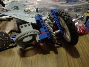
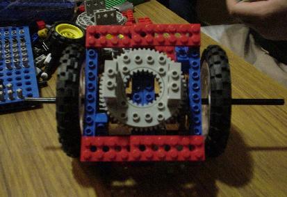
This was the first crack at a wheel unit. Here we have
a vertical gear train that would gear down the motor
45:1 (that means the motor would turn 45 times before
the output axle turns
once).
Though this design had good
width and height, it was way too long. Two of these
bad boys side by side would exceed threshold dimensions. |
|
|
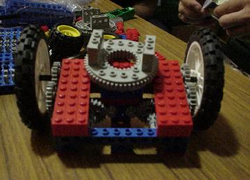
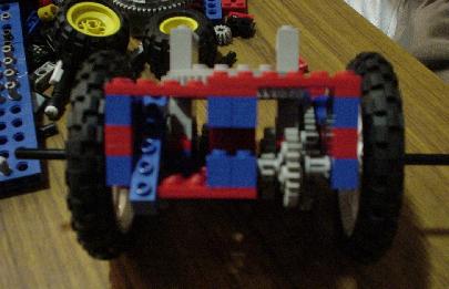
Alberto's design
This creation was light, had built in compartments
for dual engines to power each wheel (that's one motor per
wheel), and had gear trains shaped into an L-shape.
The design had a tight look no? |
|
|
|
|
|
|
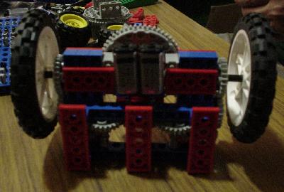
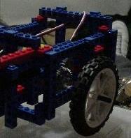
Patrick's design
This design was much more compact,
boasted faster rotation (since the wheels were closer together), and also had
dual gear trains (one to power each wheel).
You can see down both shafts to view the gear trains. Also, the
engine modification version (above), grew in dimension a tad in order
to accomodate two engines. |
|
|
|
|
|
|
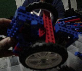
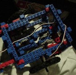
Patrick's design (with some of that Derek inpsiration).
This bad boy
became our one wheel unit. Still fairly compact, it would function also
to provide us with fast turns. It boasted two gear trains and some pulleys.
The pulleys were put in anticipation for use with shaft encoding.
New specs include dual motors controlling one wheel.... mmhmmmmm that means
there were still four motors, but each wheel would have two motors powering
it. Why? The more motors powering a wheel, the closer you get to the actual
speed you want that tire to move (more power tends to thwart pressure
and weight from above, as well as other factors)
That bad boy looks pretty "open" huh? Yeah... that adds to the lightness... |
|
|
|